Allen-Bradley 1794-IE8H Specifications Page 25
- Page / 62
- Table of contents
- BOOKMARKS
- 1
- Catalog Number Bulletin 1794 2
- Reference Manual 2
- Important User Information 3
- Introduction 4
- Manual Set-Up 4
- Understanding Terminology 4
- Preface 2 5
- SIL Policy 6
- SIL2 Certification 7
- Proof Tests 8
- IMPORTANT 9
- SIL2-Certified FLEX I/O 10
- System Components 10
- 1-6 SIL Policy 11
- SIL Policy 1-7 12
- Hardware Designs and 13
- Firmware Functions 13
- Difference Between PFD 13
- SIL Policy 1-9 14
- 1-10 SIL Policy 15
- SIL Policy 1-11 16
- SIL Compliance 18
- Distribution and Weight 18
- Response Times 18
- 1-14 SIL Policy 19
- ControlLogix Communications 20
- Module Fault Reporting for 21
- Related Communications 22
- Modules Documentation 22
- FLEX I/O Modules 23
- Using Digital 24
- Input Modules 24
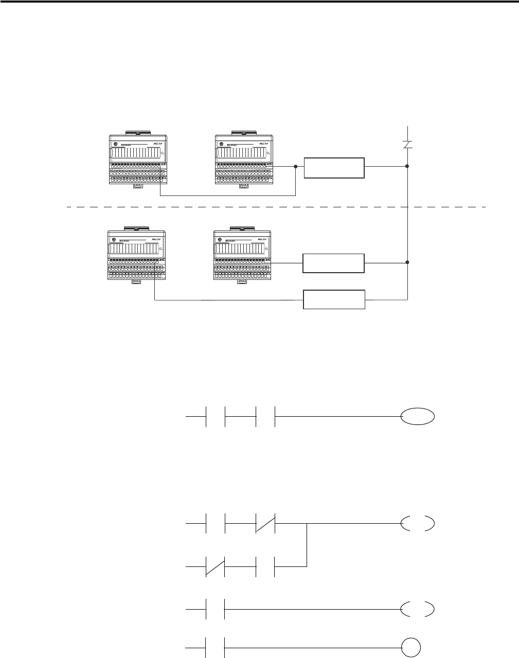
- Wiring FLEX I/O Digital 25
- Figure 3.4 26
- Output Modules 27
- Relay Module 28
- Using Analog Input 29
- Figure 3.7 30
- Wiring FLEX I/O Analog 31
- 3-10 FLEX I/O Modules 32
- Wiring the RTD Input Module 34
- Using Analog Output 35
- Monitoring input 36
- FLEX I/O Modules 3-15 37
- Checklist for SIL Inputs 40
- Checklist for SIL Outputs 41
- 3-20 FLEX I/O Modules 42
- General Requirements for 43
- Application Software 43
- Application Program 45
- Failure Estimates 47
- A-2 Failure Estimates 48
- Failure Estimates A-3 49
- A-4 Failure Estimates 50
- Failure Estimates A-5 51
- A-6 Failure Estimates 52
- Failure Estimates A-7 53
- A-8 Failure Estimates 54
- Failure Estimates A-9 55
- A-10 Failure Estimates 56
- 2 Index 58
- Rockwell Automation Support 61
- Documentation Feedback 61
Related products and manuals for Networking Allen-Bradley 1794-IE8H
 (200 pages)
(28 pages)
(200 pages)
(28 pages)
 (20 pages) (146 pages)
(112 pages)
(239 pages)
(20 pages) (146 pages)
(112 pages)
(239 pages)
© 2020, manymanuals.com. All rights reserved. | 1.800 s |
 Manymanuals.com
 Manymanuals.de
 Manymanuals.fr
 Manymanuals.it
 Manymanuals.pl
 Manymanuals.cz
 Manymanuals.es
 Manymanuals-pt.com
Comments to this Manuals